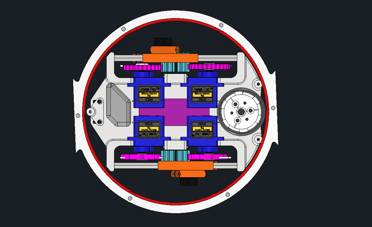
I just completed a V1 full CAD, legs, electronics, weapon, everything. I then rapidly realised it needs more work.

I've learnt a lot from this version, come up with many solutions that will likely make the final version.
These are similar to the previous development version. The packaging has been tightened with the servo gear now on the back of the horn, and the overall height was increased slightly, allowing a larger gear on the servo, hence a greater top speed.

One neat feature is the servos are rotated 180 degrees, so they're closer together. In the previous version the idler gears spun on a bolt mounted to the frame. The rotated servos need this space to mount. So this version has the servo mounting holes also be the holes for the idler gears bolt.
Originally this was just a test of the frame, so I wasn't planning on doing any weapon, but as I developed I realised that in order to have a good test of the frame I need at least a plan for the weapon. So I modeled it.
The normal solution for letting a big round thing spin is a bearing. Unfortunately one big bearing would probably weigh more than the robot. So instead I'm using three small bearings, spaced around the robot. One of these is able to move in and out (when unbolted) to enable me to get the perfect tension.
To constrain it axially, the bearings run in a v-slot on the weapon disk. These would be machined by JLCPCB or PCBWay.
I've gone back and forwards between friction and gear drives for the weapon. I ended up deciding on friction because it's way easier to machine and will hopefully deal better with impacts.
For all the cool design features, this design has many major flaws. The body is all 3d printed, very weak and heavy. There is exactly 0 top armour ( also nothing to hold in the battery... ). The mounts for the ring bearings are also very week, and have a very thin wall.
Luckily a V2 CAD is already done, details soon hopefully.