Full transparency, this entry discusses two versions of the leg that never made it out of the CAD stage, but I think they're interesting, so I'm going to talk about them.
As mentioned in the previous article, the current leg is way too tall and heavy. After some further kinematic analysis ( read playing with sliders in desmos ). I did conclude the double leg concept doesn't work. :(
Here, the red line is the stepping motion.
The green line represents the rack positions for all the points needed to follow the step path. The x coordinate is the position of one rack, and the y coordinate is the position of the other.
The blue line is proportional to the distance the servo's have to move as they follow the step path.
With the new dimensions, with much smaller racks moving much less, the height of the leg can be way shorter. This was mostly modelled when I started to consider the problems.
With this concept there are two main problems.
The horizontal translation is from the rotation of the leg. This means as the steps get longer the servo's have to move further to achieve the same translation. This limits top speed, and also requires more vertical space, so a larger and taller robot. As you make the step shorter you have to raise and lower the leg more often, also reducing speed. Further the servo is constantly accelerating and decelerating, drawing more current and limiting the speed.
To lift up and lower the leg requires raising and lowering both racks, so the more ground clearance, the taller it has to be.
Or more accurately it's side. Using horizontal racks intead of vertical means the easy direction is horizontal, the height of the module is easier to control since it's constant. Lifting the leg is done by rotating it.
Another benefit is the double leg concept actually works.
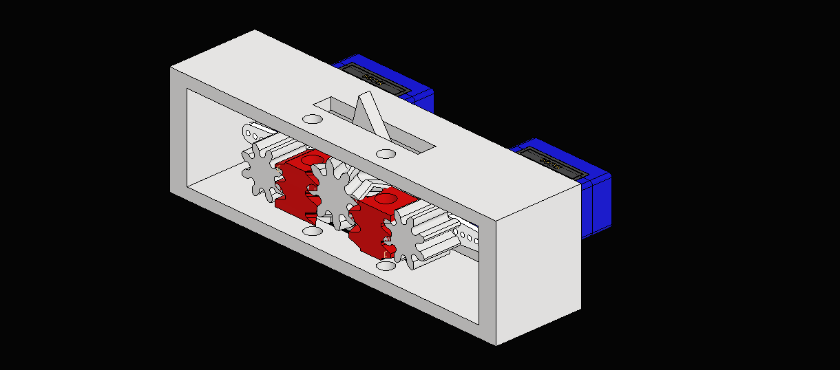
The plan was to drive the racks with Threaded Rod (Throd). The throd in turn would be driven by a gear train and a pair of N20 gearbox motors. It would've used a pair of linear potentiometers as encoders for the racks.
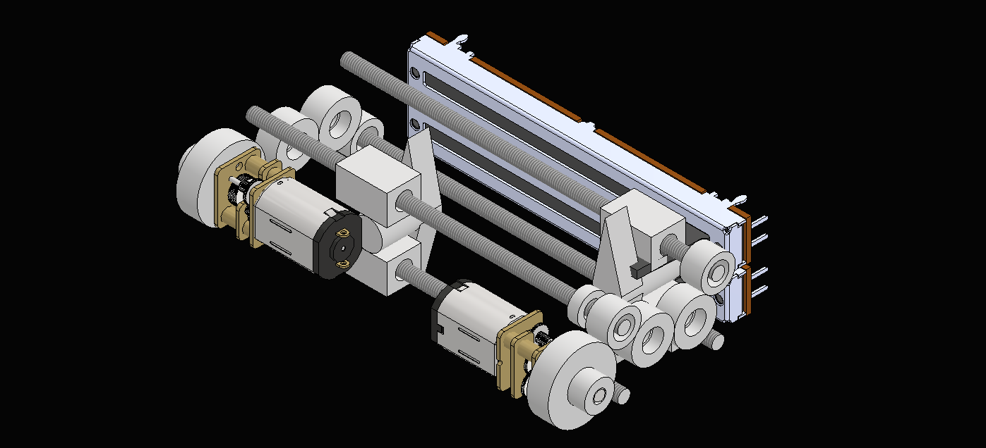
A small throd like m4 also has a very small pitch, so to achieve a reasonable speed it needs to be spun very fast. The concept also requires lots of gears, so lots of high speed moving parts, lots of bearings, lots of failure points, lots of weight.
I bought some parts for this concept, but scrapped it before printing any parts.
I have a new, fully working concept. Tune it right now to find out more!